The keystone correction doesn’t currently use the entire width or height of the projector’s DLP chip. You can see this in a dark room, there is a 5-10% border on the left and right that is unused, regardless of the keystone angle. And if you set the projector at an angle up against the wall, up to 50% or more of the vertical height of the DLP chip is wasted by black bands at the top and bottom of the image. Cropping at the sides and top of the image is not just a waste of DLP pixels and resolution, but it also decreases the total light output of a video frame.
I would really like a keystone correction option that allows for the image to always be stretched to the full height of the sensor, and clipped to the edges of the sensor if necessary. This way, the image content can still be keystone-corrected by trapezoidal stretching, but the maximum number of DLP pixels will be used. On the wall or screen, it may look like there is an “upside down keystone” cropping applied to the sides, which is the DLP chip’s projection footprint, but the content will look correct.
There has been a discussion about this earlier where we haven’t reached a complete understanding if any underscan is going on. Best way to determine how much of the black pixels you see that are real and how many that belongs to the inactive pond of micromirrors is to compare to the size of the splash screen. That screen uses all of the active pixels, so if your image without keystone correction is smaller than that then there’s some odd underscan going on. Link here: Projection isn’t projecting full size
It’s very easy to see the wasted pixels in a dark room, since the projector’s blacks are not perfectly black. If the keyhole correction is extreme (e.g. if the projector’s horizontal alignment is way off), then I have seen as much as 70% of the pixels wasted, due to all the keyhole distortion.
Of course, the point was that (in this DMD in pixel shift mode) you have what will look like 40 black pixels on each side which are in fact inoperable and won’t ever turn on. That’s why I was asking about the size difference between the power on splash screen and your video frame.
For digital keystone correction you may lose a lot of pixels and brightness, but for most use cases it will not be that extreme. I would think focusing will start to become a major problem first?
Are you saying that when the projector is aligned straight to the wall, there is still an uniform frame of black pixels all around the image?
Do they light up in white when the projector is turned on and the splash is showing? @wernerj, 5-10% sounds too much for POM?
Of course, the point was that (in this DMD in pixel shift mode) you have what will look like 40 black pixels on each side which are in fact inoperable and won’t ever turn on.
What do you mean by this? DMD? Pixel shift mode? The DLP can definitely use all the available pixels, because it does so on the home screen with keystone correction disabled, but the outermost corners of the trapezoid with keystone correction enabled do not touch the outer edges of the DLP displayable area, they are set in from the side of the dark gray rectangle which is the DLP chip’s total display area. This is simply a waste.
Are you saying that when the projector is aligned straight to the wall, there is still an uniform frame of black pixels all around the image?
I found that my projector’s horizontal alignment calibration was off by more than 45 degrees. I found the option in the settings to re-calibrate it. But if you want to see what I mean, hold your projector pointing 45 degrees downwards and tell the projector to calibrate its horizontal orientation, then turn it back to flat. Project against a white wall in a dark room. You’ll see (1 - sqrt(2)/2) = 30% of pixels (for a 45 degree tilt) will be wasted in total between top and bottom, and set to black, plus another 10% or so will be wasted at the sides for the black triangular cutouts beside the trapezoid. The original horizontal calibration was so bad that I would say more like 55% of pixels in the DLP were wasted, meaning that not only was the image warped (the aspect ratio was wrong and the keystone correction was wrong), but the total image brightness was 45% of the possible output for the lamp and DLP chip, and the image was smaller than it could be too.
The DMD (Digital Micromirror Device) is the part of a DLP-based light engine that contains the pixel-forming mirrors in the DLP system. Pixel shifting is how this particular DMD in this projector can display 1920x1080p video at 60Hz. The DMD itself contains a total of 1000x580 micromirrors where the center 960x540 can form active pixels. With a four-way actuator these form the 1920x1080 pixels you expect to see on the wall/screen, with an additional 40 pixels on each sides that always stay black. Your screen size when having keystone correction disabled seems to fill the entire active area, so I agree with you that something seems to be off with the correction. We already have learnt about the lack of linearity correction for 4-corner correction, that’s being worked on.
That’s odd. There’s no way the accelerometer can have such a massive hardware offset, so my guess is that it wasn’t placed on a level surface during QA testing and that the projector retained the setting. I still haven’t received my PPM so I haven’t been able to verify the applied corrections myself yet. My goal is to have 1:1 pixel mapping avoiding any form of geometry correction (also maximizing the number of active pixels/mirrors in the process).
What are you discussing here guys
I didn’t read in detail, but digital keystone correction will always lose pixels. How else would it work? The optics don’t physically move.
The claim is that the trapezoid keystone corrected image fed to the DMD does not touch the active mirror bounding rectangle (meaning that it would be too small, wasting additional pixels). There’s no doubt that there will be a massive loss of pixels (and light output) at extreme angles. It’s not a UST after all.
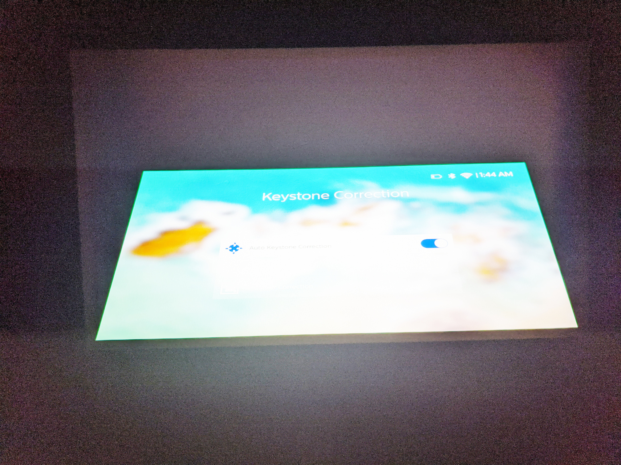
Here are some examples, with the brightness and contrast enhanced in post-process so you can see the edge of the DLP area around the image.
With keystone correction disabled: (Actually I was wrong, there is a small dark gray border around the image, within the DLP area, that is not projected onto.)
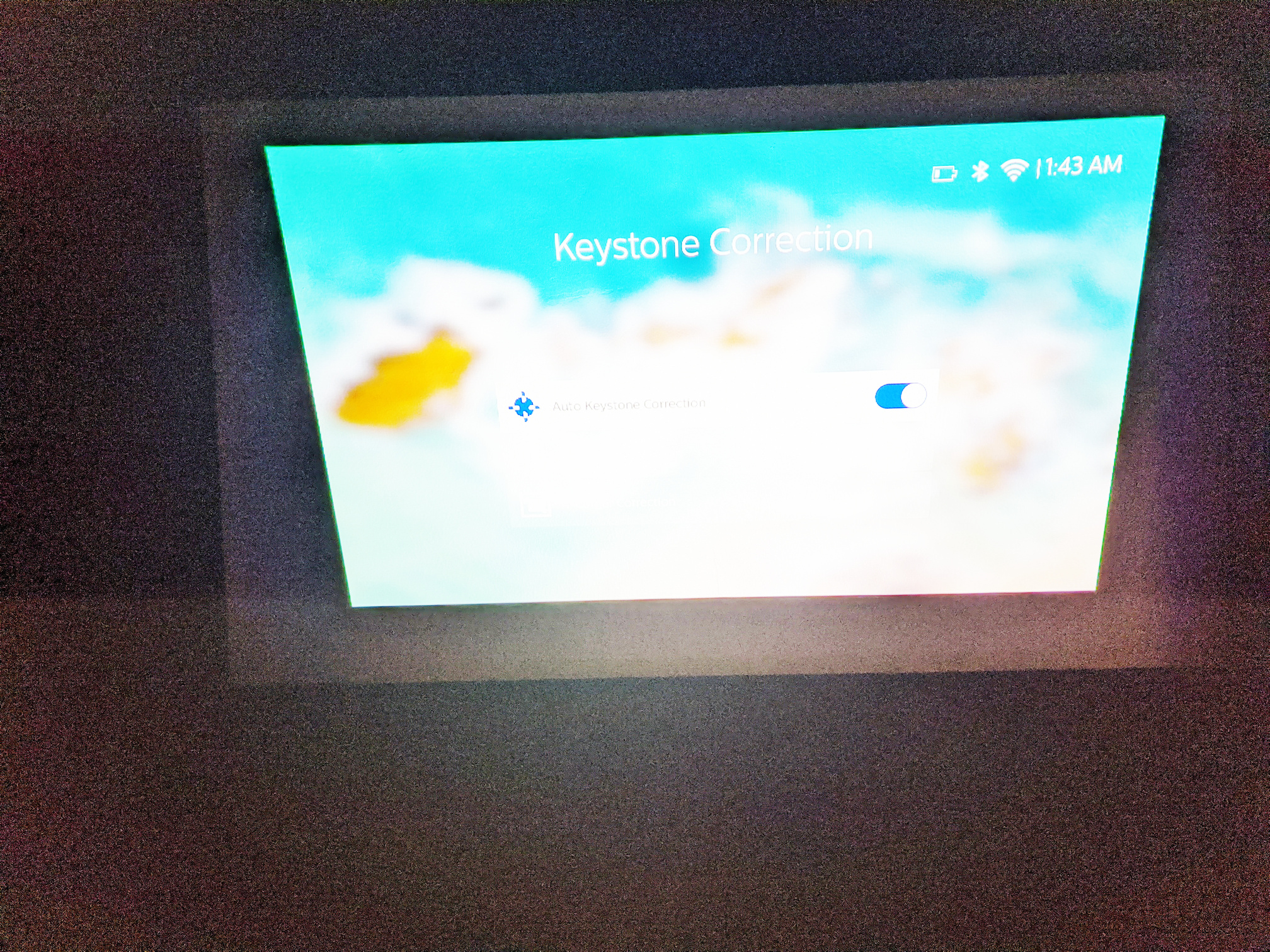
With keystone correction enabled, with incorrect horizontal calibration. Pixels are wasted at the top and bottom of the image, and the outer corners of the trapezoid don’t touch the outer edge of the DLP rectangle. (However the amount in this case is the same as for the above image with keystone correction disabled.)
However in the following case, the outer corners of the trapezoid are really far in from the sides of the DLP area. This indicates a bug in the code that calculates the trapezoidal transform. Way more pixels are wasted than are needed at the sides. And actually I have seen the outer corners of the trapezoid even further from the sides of the DLP addressable area than this. It’s arbitrary and seems random as to how much horizontal space the trapezoid actually takes within the DLP area.
But also in both keystone correction cases above, especially the first of the keystone examples massive numbers of pixels are additionally wasted above and below the image, and since the brightness of each DLP pixel has a maximum limit, that means the overall brightness of the keystone-corrected image is decreased compared to the maximum limit if all pixels were used. What I’m suggesting is to have an option to always stretch the image to the full height of the DLP chip (DMD). Then cut off the sides of the image, either trapezoidally as shown above (so that the image looks rectangular on the screen), or just as a third option, use the entire DLP chip (which will look trapezoidal on the screen if the projector is not projecting perpendicularly to the screen).
4-corner correction for internal sources using the GPU vs vertical keystone correction using the DLP chipset are two different things, that’s correct.
Thanks for the examples, very helpful! The first two images seems to be correct (the border around them should be the inactive “pond of micromirrors”. If you have the possibility to take a photo of the white splash-screen you should be able to see the exact same black border around that.
The third one most certainly doesn’t look right. The only time it should look like that is if there was digital “zoom” applied as well to reduce the image size. If you’re at 100% image size the trapezoid shape should always touch the edge of the active area.
Zoom is at 100%, and I didn’t change it for the third image. You can reproduce this yourself. Just hold the projector still at an angle between 10 and 80 degrees from horizontal, either tipped forward or tipped back, and reset the horizontal calibration, then wait until the calibration and autofocus is complete before moving the projector. Try it a few times. You’ll see the trapezoid width will vary. It’s definitely a bug.
Not 100% sure the issue is exactly this, but keystone has been addressed in the current beta. I believe @lukehutch’s issue was happening because it was performing a calibration every time the keystone was turned off and on, which could be at slightly different angles. This is fixed now.